I Put Two Overpowered Motors on My Wheelchair

Vladislav Mihov
· 6 min read

Manual wheelchairs are cheap, light, and everywhere. Electric wheelchairs are none of those things. A decent one runs several thousand euros, and you're buying a whole new chair, not upgrading the one you already have. So: what if the electric part was just something you bolted onto the back of a normal chair?
The base chair
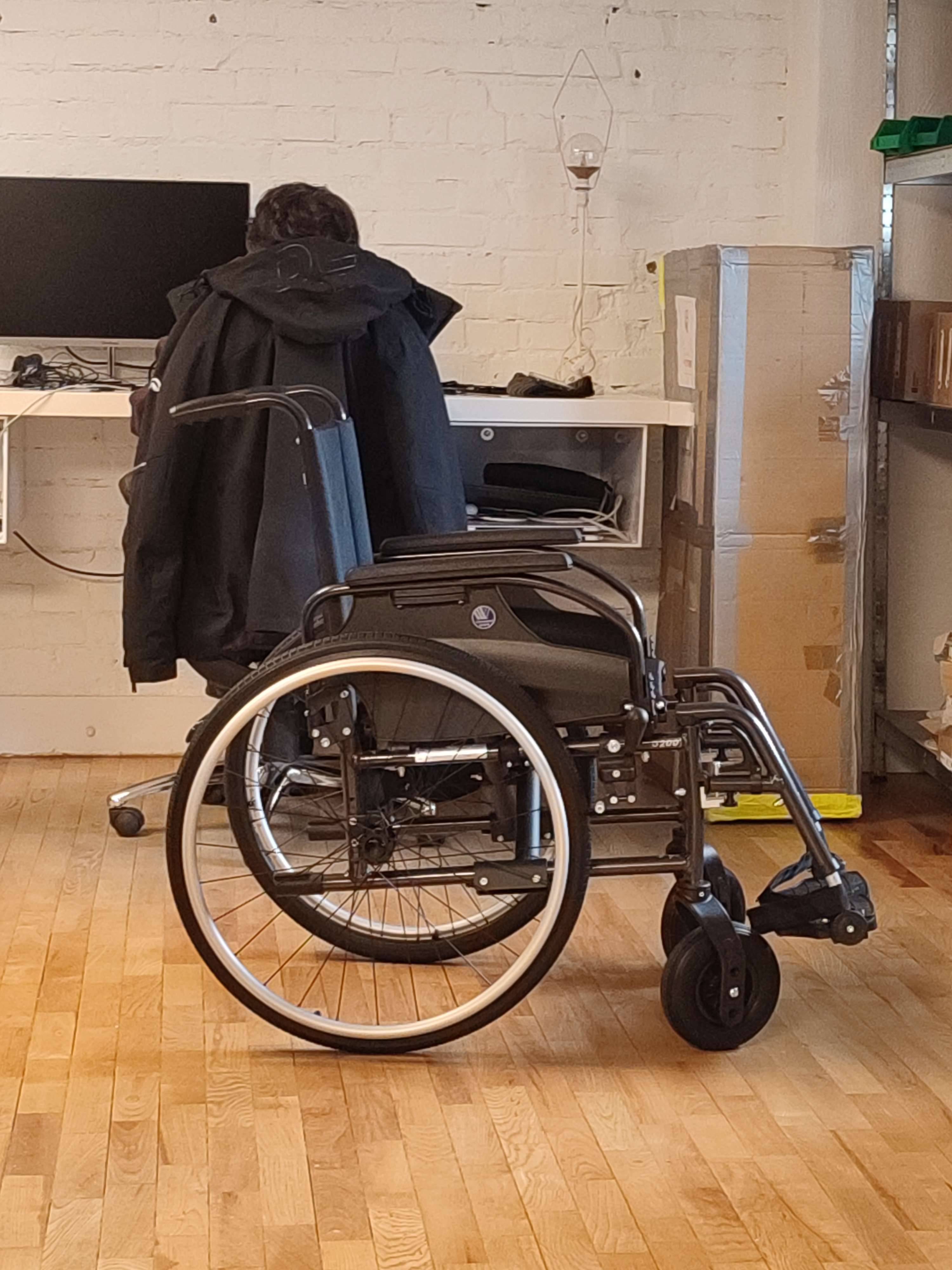
Every add-on project starts with a victim. Ours: a stock manual chair, nothing special about it. Nothing on the chair itself gets touched. The drive unit comes off the chair's own frame.
Before any metal got cut, the drive unit existed only as a Fusion 360 assembly. Drag it around.
drive unit frame, solid geometry, decimated for web
Cutting the frame
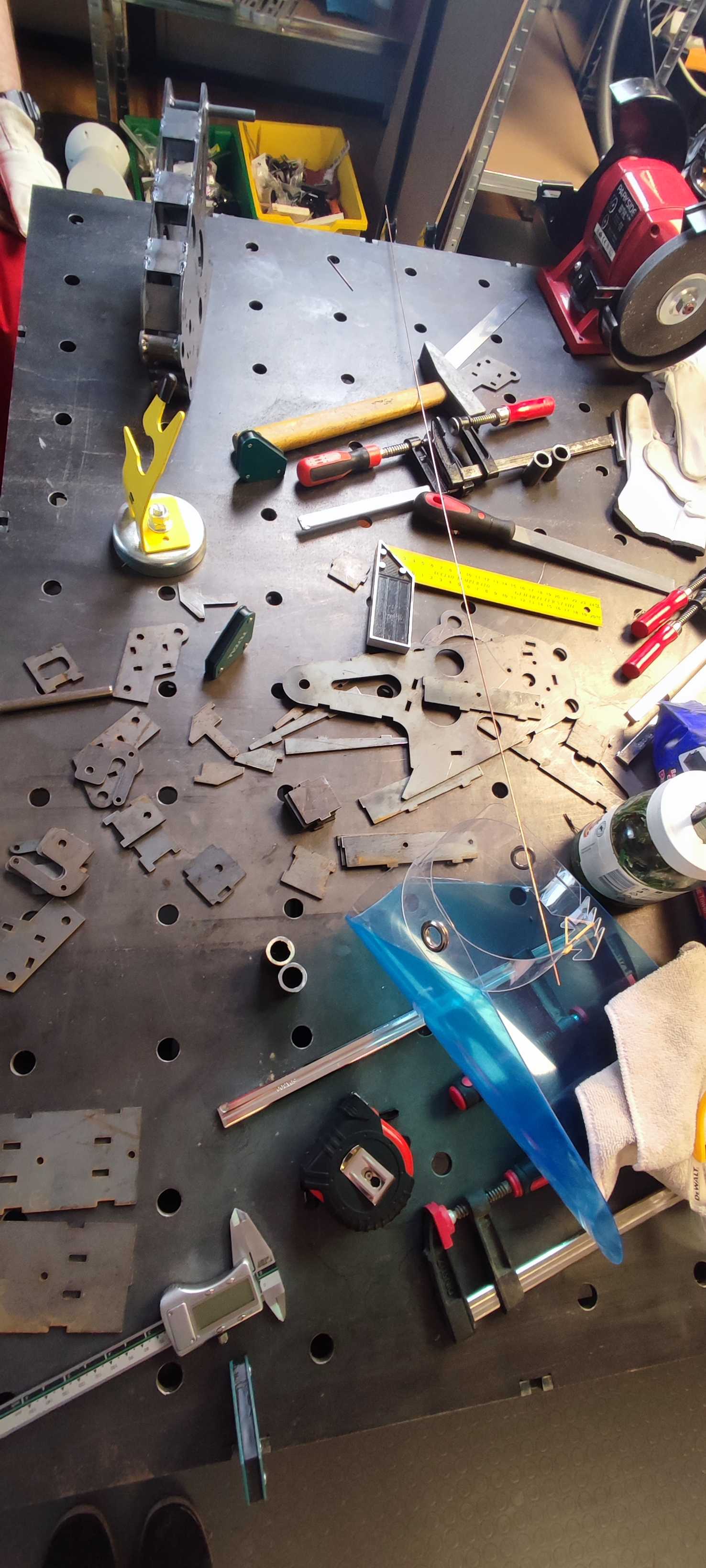
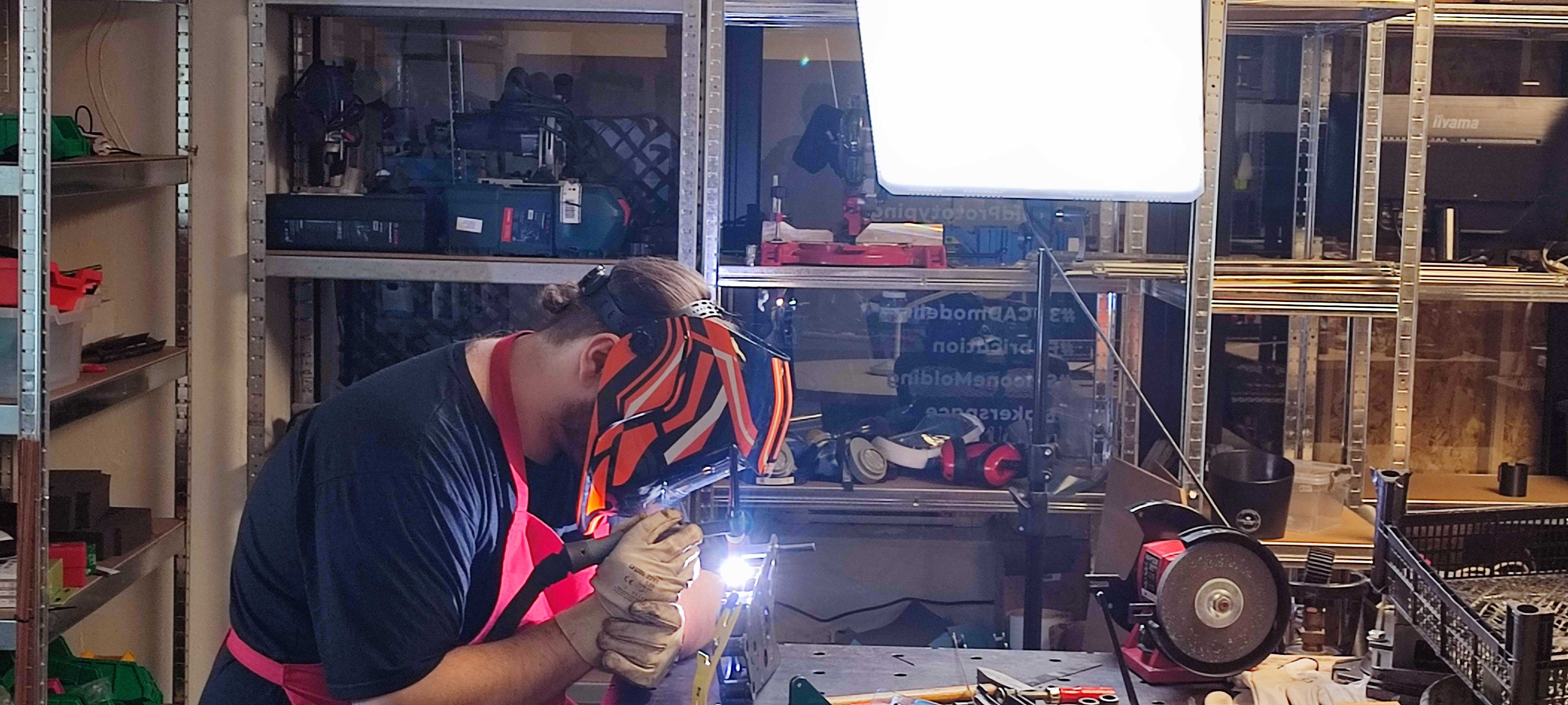
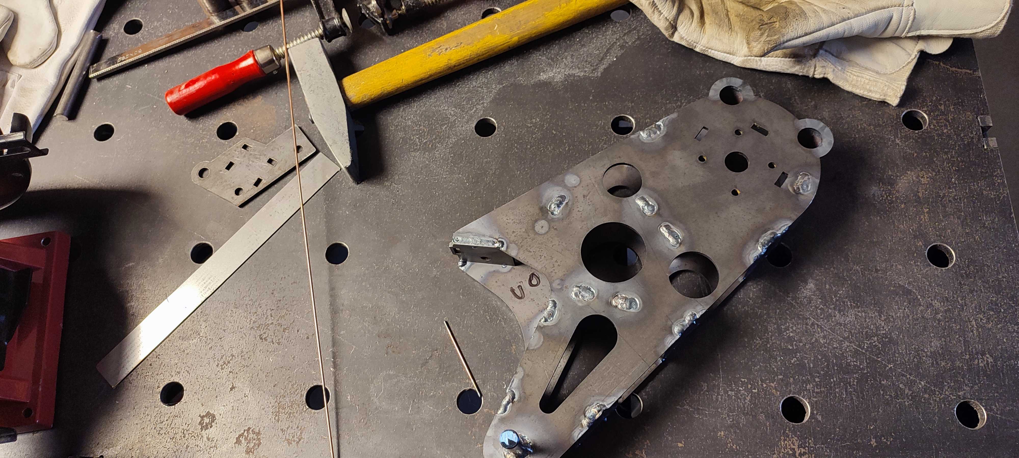
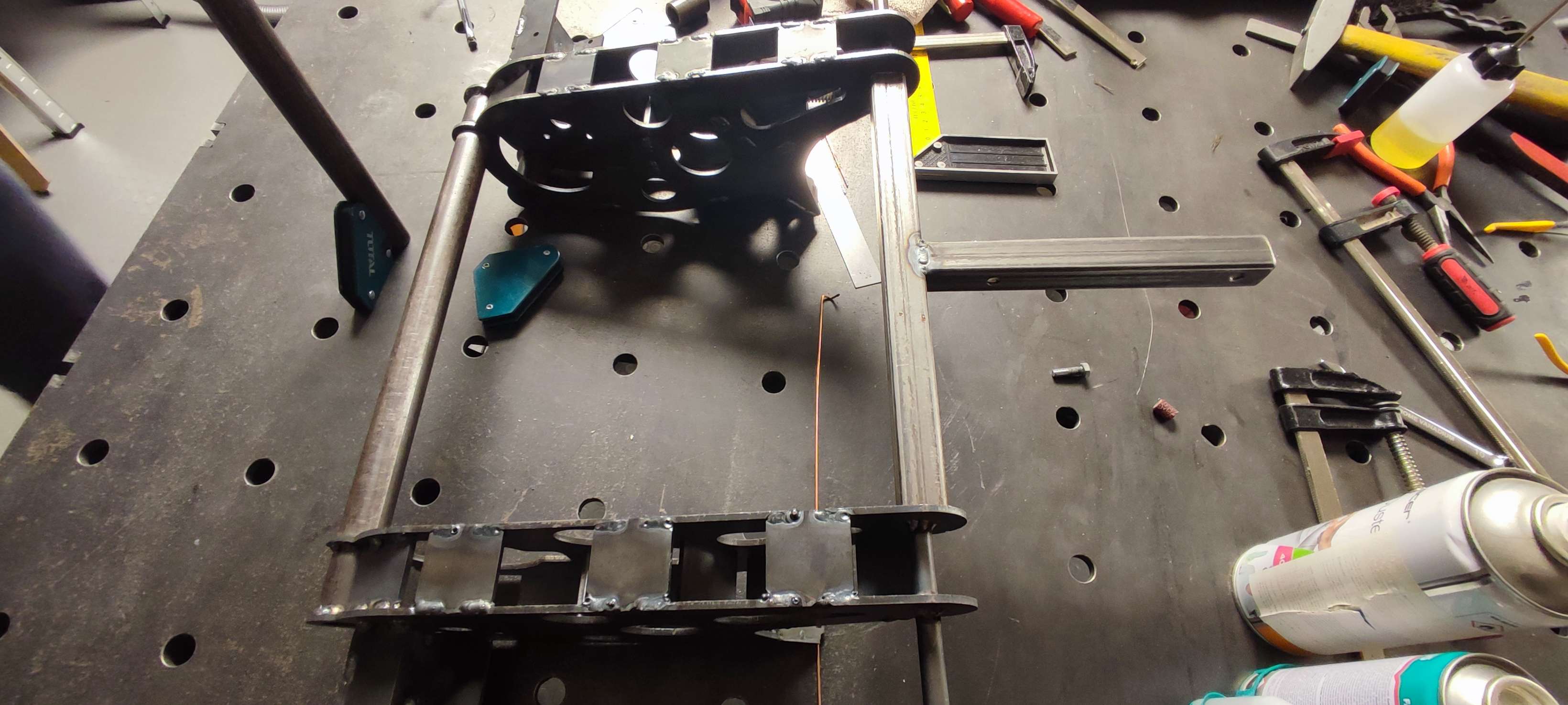
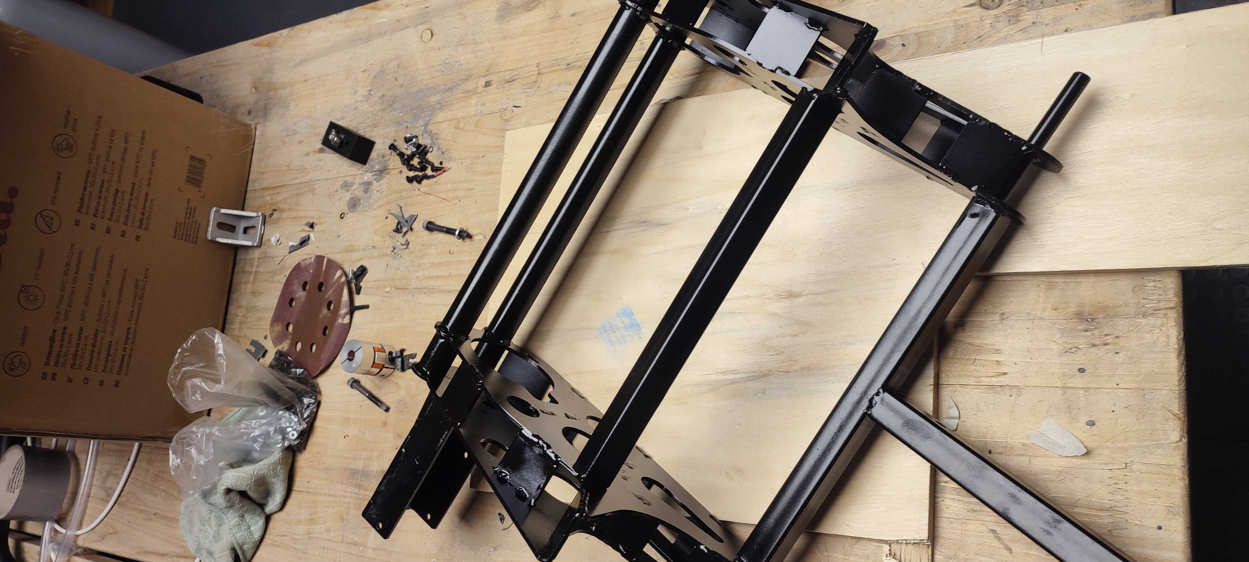
The frame is mostly laser-cut sheet steel, folded and welded into a cage that straddles the rear axle. The parts around the motor mount are lathe-turned, plus two 3D-printed holders. Electronics and joystick enclosures are 3D-printed too.
Powertrain
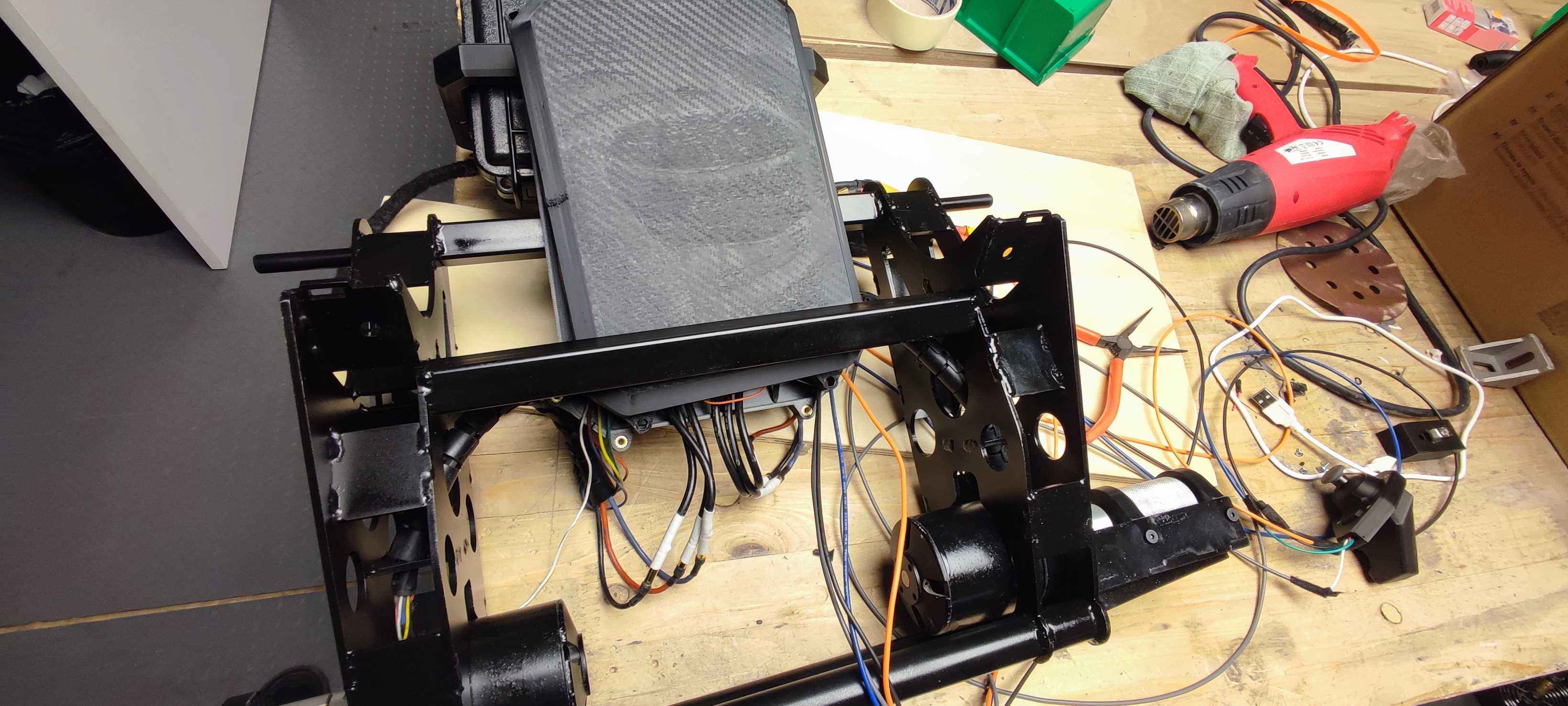
- Two 2kW motors, one per wheel
- Flipsky dual VESC, one board with two motor outputs, wrapped in a carbon-fiber-look 3D printed enclosure
- 10S4P battery pack, 42V nominal, up to 80A discharge
- Arduino Uno reading a joystick and turning it into VESC commands over UART
The firmware
const int PIN_X = A0;
const int PIN_Y = A1;

const int CENTER = 512;
const int DEADZONE = 40;

const float MAX_CURRENT_A = 12.0f;   // start here, increase later

const uint8_t ID_OTHER = 63;         // other VESC over CAN

float joyToNorm(int v) {
  int d = v - CENTER;
  if (abs(d) < DEADZONE) return 0.0f;
  float n = (float)d / 511.0f;
  if (n > 1.0f) n = 1.0f;
  if (n < -1.0f) n = -1.0f;
  return n;
}

void loop() {
  float x = joyToNorm(analogRead(PIN_X));
  float y = joyToNorm(analogRead(PIN_Y));

  // Tank mix
  float left  = y + x;
  float right = y - x;

  left  = constrain(left,  -1.0f, 1.0f);
  right = constrain(right, -1.0f, 1.0f);

  float iLeft  = left  * MAX_CURRENT_A;
  float iRight = right * MAX_CURRENT_A;

  setCurrentLocal(iLeft);
  setCurrentOther(ID_OTHER, iRight);

  delay(20); // 50 Hz continuous updates
}
MAX_CURRENT_A is capped at 12A on purpose. Better to be underpowered than to launch someone into a wall.
void sendPacket(const uint8_t *payload, uint8_t len) {
  uint8_t frame[260];
  uint8_t idx = 0;
  frame[idx++] = 2;
  frame[idx++] = len;
  for (uint8_t i = 0; i < len; i++) frame[idx++] = payload[i];
  uint16_t c = crc16(payload, len);
  frame[idx++] = (c >> 8) & 0xFF;
  frame[idx++] = c & 0xFF;
  frame[idx++] = 3;
  Serial.write(frame, idx);
}

// other VESC via CAN-forward
void setCurrentOther(uint8_t can_id, float currentA) {
  int32_t mA = (int32_t)(currentA * 1000.0f);
  uint8_t p[7] = {34, can_id, 6,
    (uint8_t)((mA >> 24) & 0xFF),
    (uint8_t)((mA >> 16) & 0xFF),
    (uint8_t)((mA >> 8) & 0xFF),
    (uint8_t)(mA & 0xFF)
  };
  sendPacket(p, 7);
}
Command ID 34 is COMM_FORWARD_CAN. Wrap a normal "set current" command (ID 6) inside it, address the second VESC's CAN ID, and the first VESC routes it over the bus.
Riding it
Tuning is done through the VESC app over USB. Everything else through the Arduino IDE.

Written by
Vladislav Mihov
Founder, Synaptic
Vladislav leads R&D and software delivery at Synaptic, working with hardware makers, product teams and startups to ship the software their systems run on.
LinkedIn